
| |
| ELSA-Facility | |
| Accelerator physics: | |
| Home page | |
| Group members | |
|
|
Accelerator |
| Research & development | |
| Publications | |
| Teaching | |
| Experiments at ELSA: | |
| Hadron physics | |
| Polarized target | |
| Test beam | |
| Informations for users: | |
| Beam schedule | |
| Accelerator status | |
| SFB/Transregio 16 | |
| Radiation protection | |
| Job offers | |
| Additional links | |
| Guided tours | |
| Contact | |
 |
Deutsche Version |
ELSA control system
Hardware
Most modern accelerator control systems build on the same principles: a distributed architecture and standardization towards open systems. The ELSA control system is specially designed for high bandwidth on all layers and, due to envisaged future upgrades and expansions, seamless extension in capacity and capability. It combines control, simulation and modelling together with online beam diagnostics in one homogeneous environment. The following guidelines were set for the design:
- The basis is a distributed system with several loosely coupled logical layers providing failsafe operation and allowing scalability. The intelligence and computing power for the handling of local tasks and computations is transfered to lower layers whenever possible.
- Transparent behaviour of the complete control system and in particular of the communications between the logical layers of the control system from the viewpoint of both the user and the application developer.
- The widest possible use of standards for all hardware and software components allow for a minimal implementation time and simplify service and support.
- A common development platform for all software components on the workstations and use of development tools for software engineering and documentation.
-
 The presentation layer uses the X11 windowing system.
A man machine interface is providing the interactive control of all parameters. Other
user oriented applications like orbit correction or general purpose machine
diagnostics are also activated on the presentation layer.
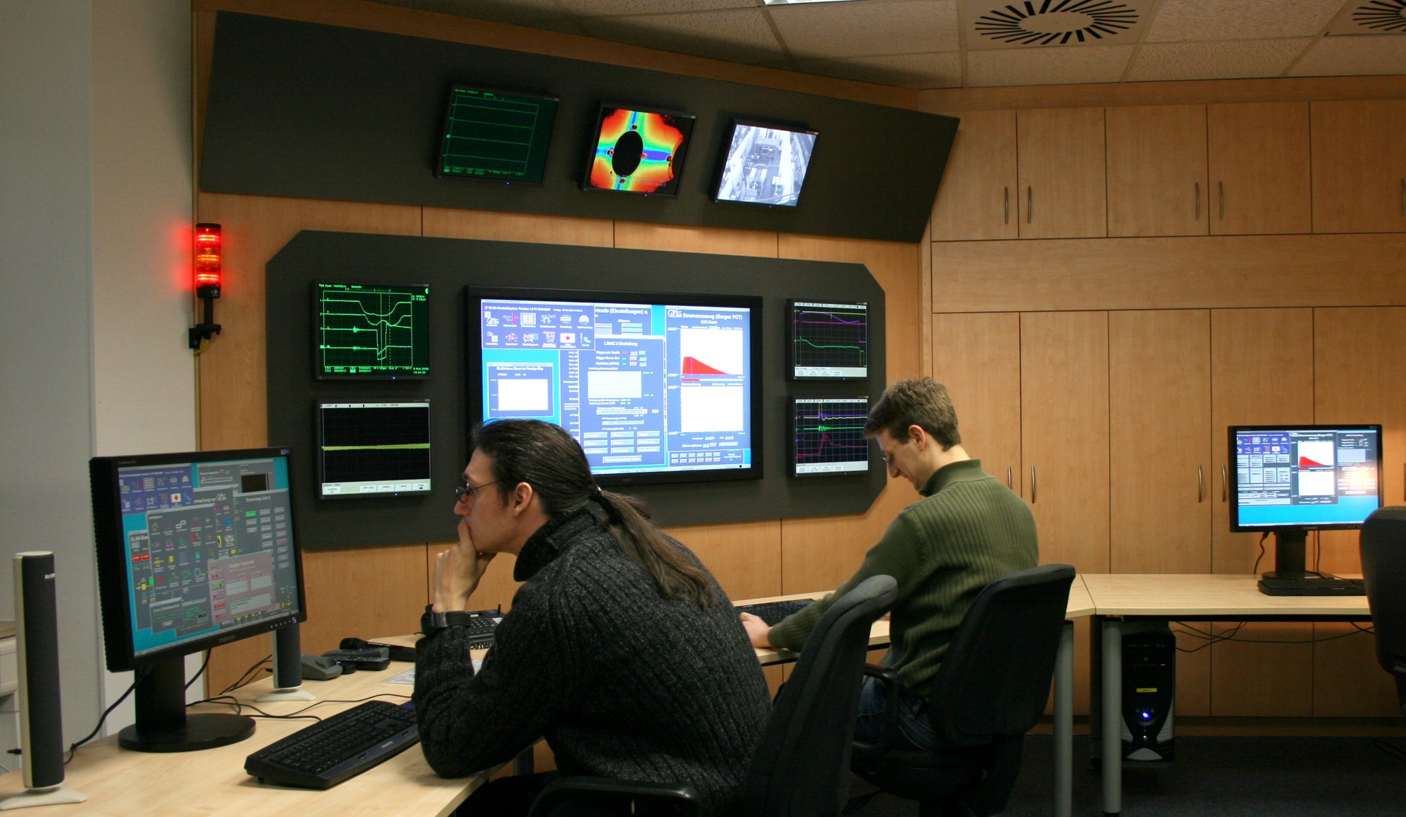
In the control room four operator consoles are in use.
The presentation layer uses the X11 windowing system.
A man machine interface is providing the interactive control of all parameters. Other
user oriented applications like orbit correction or general purpose machine
diagnostics are also activated on the presentation layer.
In the control room four operator consoles are in use.
- The control layer was originally developed an HP workstations
running the operating system HP-UX.
Actually, the control layer runs on a PC (CPU i7-6700K and 48 GB memory) with Linux. The control system can be easily started on additional PCs.
The architecture and software of the control system allows for the seamless addition of further computers for new subsystems. The control computers manage a distributed, memory resident online database, which acts as a mirror image of the accelerator state.
An archive engine (based on the non-relational database Hypertable) logs the values of a accelerator parameters for later analysis. - The process control layer performs data reduction and runs control
and measuring tasks. It is built of VME based components and PCs with Intel Pentium CPUs.
The VME systems are equipped with Motorolas MP68030
and MP68040 CPUs (each equipped with a 68882 co-processor).
On the VME systems we use the real time operating system VxWorks (developed
by WindRiver Systems).
All VME crates of the process system are
diskless; they boot over the network from the computers of the control
layer.
On the PCs Linux is used as operating system.
- The fieldbus layer interfaces all the devices of the accelerator complex which do not require high data throughput and connects them to the process control layer. It is realized through VME components, the MACS fieldbus system (based on Intels 8085 CPU), which has been developed in-house, and several PLC systems.
At present (March 2017), 25 VME processors, 15 Linux PCs, 17 PLCs and approximately 45 MACS fieldbus computers are attached to the system.
The process control and the fieldbus layer together form the process system.
The communication system between the control and the process system is based on Ethernet (IEEE 802.3). The consistent realization of the process system with VME components and a uniform operating system allow for a homogeneous communication system based on standard protocols (TCP and UDP on top of IP) for the complete control system. The remote inter-process communication on all layers is realized through synchroneous and/or asynchroneous message exchange. High bandwidth data paths will be realized exclusively by using TCP socket data transfers or by ONC-RPC calls.
Software
The efficiency and flexibility of a control system is mainly determined by its software. The software of the control system performs tasks which in many ways resemble the duties of a distributed operating system. The results arising from research in the field of distributed systems are therefore fundamental for the design of such an accelerator operating system.
The process system contains applications for data acquisition, equipment control, monitoring and alarms and for complex real-time tasks like feedbacks and magnet ramping. Each application consists of a set of one or more concurrent threads synchronized by the VME operating system kernel. These applications send data to the control layer in regular intervals (e.g. tune monitoring), triggered by observed parameter changes (e.g. status conditions) or perform a task on request (e.g. image acquisition and processing).
Each computer of the control layer is managing a memory resident online database representing one part of the accelerator complex. The set of online databases on the individual computers is linked via horizontal communication paths, such that only a single, distributed database is seen which allows for transparent access to all the informations pertaining the accelerator. The relation of given parameters to individual computers is not explicitly seen by high level applications and process layer software alike.
On the control computer runs a "rule engine" (i.e. a set of processes fed with patterns of accelerator parameter changes) which elaborates abstract rules and correlates machine parameters. A set of rules will handle the algorithmic mapping from hardware dependent parameter sets to machine physics parameters. Other rules will implement heuristic recipes for easy management of complete subsystems. Rules may be activated or deactivated during normal operation. The control system itself uses the concept of rule engines to monitor and survey its own performance and utilization. Whenever bottlenecks in CPU load or network traffic are observed, warning or notice events are generated and distributed to the log system.
The man machine interface is the interactive tool from which the individual components of the ELSA accelerator are controlled. In order to avoid confusion and to minimize the learning time, the interface builds on ergonomic and logical concepts which allow for an intuitive understanding of its operation and of the operation of the devices it controls.
Some menus of the ELSA control system
(If you want to look at more examples of control menus, please click here.)
Virtual control menus allow users to operate on the graphical representations of a large set of devices like switches, knobs, sliders, digital and analog indicators, whose behaviour is equivalent to that of the real instrumental devices. The menus can be generated interactively by means of a graphical editor in a menu driven way without writing a line of code. The connection with the online database and the underlying servers on the lower layers is automatic and completely transparent.
 Printer version
|
Deutsche Version
|
Imprint | Data privacy statement |